Tuesday, April 23, 2013

9. Batteries


Don’t forget that typically, rechargeable batteries give you a lower voltage than non-rechargeable batteries.  The performance of rechargeable batteries is different from that of non-rechargeables.  As the Alkaline (non-rechargeable) battery discharges with use, its voltage decreases steadily.

NiMH and Li-Ion batteries start off with a lower voltage about (1.2 V to 1.3 V) than Alkaline (typically 1.5V for Alkaline).  However rechargeable batteries maintain the initial level until they are almost fully discharged.

Rechargeable batteries are more expensive but because they last longer, they are more cost-effective.  Rechargeables allow re-cycling so that spares can be re-charged while your other set is being used in your project.  Using standard batteries could be much more expensive (and a bit of a pain).


For all the information you're likely to need for hobby purposes, there is an excellent Adafruit article here: http://learn.adafruit.com/all-about-batteries


8. The Voltage Regulator


This is a very useful component, and can be used safely to ensure that the voltage you’re delivering to your 3.3 V (3V3) project (for example) will not be exceeded.  There are different versions available for different voltages.

A very useful device is the MCP1702 3.3 V Regulator, and here is a cheap way of using it to get up to 250 mA at 3.3 V from an input anywhere between 3.85 V and 13.2 V (http://www.core.st/projects/AVR32_Starter_Kit/3_3_V_power_cheap.html):

The TO-92 describes the overall shape (packaging) of the component. 

Alternatively, for a 3 V output up to 100 mA, from a 3.2 V to 20 V input, using an LE30CZ 3V Regulator:


Note the different values of capacitor used for smoothing the input and output voltages, and the different pin-out configuration.

Lesson to be learned - for all components - refer to the data sheet, which is normally freely available on the web.  These can be long and technical, but at least you should be able to find the correct connections to make.

There are many ways, using many different components, of making cheap and simple regulated power supplies.

7. AC Adapters


I would just like to say a word or two about AC adapters.  Although I mentioned above that this work was safe, you’re now talking about mains voltages, and you don’t mess with that unless you really know what you’re doing, so parents – keep an eye on the little children playing with electronics to make sure they haven’t graduated on to the mains type voltages. 

Here is a picture of a label on an AC adapter:


Important things to look out for are: 


  • the input voltage – the 120 V AC labelled above would not be suitable for use in the UK’s 230 V (±10 per cent) AC mains supply. 
  • the output voltage – 6V DC may need to be further regulated to suit your project.
  • the output current – 500 mA would be more than adequate for most simple projects, but for the Raspberry Pi, there is plenty of advice on the internet which recommends a maximum available current of 1000 mA (one amp).
  • polarity indication – it is very important to know which of the outer or inner parts of the plug are positive or ground.  Please note – the polarity may not be indicated at all.
The popular plug in use with such adapters is the 2.1 mm plug:  This is so-called because of the inner diameter of the plug.  The one illustrated is indicated to have positive voltage on the centre connector, while the outer connector is ground.  Breadboard-friendly versions of the socket for this plug are readily available, and extremely useful.  See the Adafruit version on the right:


2.1mm x 5.5mm female DC plug connector with center positive connection
Breadboard-friendly 2.1 mm DC barrel jack from Adafruit (this one has been mounted on a breadboard)

For Adafruit's very useful article on transformer-based AC/DC converters, go here: http://learn.adafruit.com/power-supplies/transformer-based-ac-slash-dc-converters


Remember that, especially with old or cheap units, you can’t rely on the stated output voltage and available amperage.  Always measure with a DMM.


6. Power Supply


When your project is up and running, you will possibly want to hide it in a hedge to count the number of birds coming and going from your garden bird feeder, in which case your power supply will have to be batteries.  However during the development phase, batteries are not ideal, even if you’re using the rechargeable sort.

Having searched for an ideal power supply, which is affordable (laboratory power supplies can be expensive), I spotted a really nice way of powering desktop projects:
The LM2596 DC-DC Step-down Adjustable Power Supply Module, available from Amazon at £2.99 (postage free from, I think, China) is also compact, about an inch and a half long, and can convert input DC voltages in the range 4.5V  to 40V, to 1.5 to 30V (adjustable by the little screw on top of the blue pot) while being capable of delivering current up to 2A.  To mount it on a breadboard, I had to solder a 7-pin header on to each end.

Then, to display what output voltage I will it set to, I bought a little digital voltmeter from Adafruit:


And here is the combination in action:


It is powered by a wall plug adapter which claims to produce 10V at up to 750 mA.  Here’s where the DMM came in handy – when I checked the DC voltage produced, I found that the centre pin of the 2.1 mm plug was ground, and the outer contact was at 9.97 V.  This is the reverse of what I expected, as I have found that more often the inner contact is the positive one.  Interestingly, the 10 V mentioned on the label was not too far out according to my DMM, but often apparently the quoted voltage can be way off (hopefully the DMM is more reliable).  Hence the need to measure, to get at least a neck of the woods estimate.

In the picture above, the voltmeter display is connected to the output voltage, and I tweaked the screw on the blue potentiometer so that it read just under 9 V, in case it was a bit high for the project I had in mind.

Some devices (chips) operate at 3.3 V and some at 5 V, and if you apply too much voltage, you can fry your chips, so all this measuring is really necessary.


5. A Couple of Important Tools


By this stage, I found I had been buying breadboards, LEDs, and lots of other electronic components, and although you don’t need the soldering kit with breadboards (they’re solderless), you can see from my story above, that soldering can come in at quite an early stage in your new hobby.

One essential tool is the Digital Multimeter (DMM).  This looks like a fairly complicated thing, but you’ll find it indispensible when you need to check the value of a resistor (because you, like me, probably haven’t learned the colour code for resistors), and even check that your connections, soldered or solderless, are good, with the continuity function. 

I have learned to never apply a voltage to a device without firstly checking the device’s recommended voltage range, and measuring the voltage you’re going to apply, to ensure that it is what it’s supposed to be.  Mine was very cheap, but recommended, and although it doesn’t have a capacitor measurement facility, it’s extremely useful for keeping the magic smoke away.  My DMM looks like this:
It can test voltages, currents, resistances, continuity, and even transistors.  If you can get one to measure capacitance also, that would be useful.

Now, coming from a scientific background, and being a real gizmophile, I thought I would splash out and get a Digital Storage Oscilloscope (DSO). 

This is also a complicated looking piece of equipment, and can sometimes take a lot of patience to get it going.  I was delighted to find the DSO Nano, the same size and appearance as a mobile phone, and at an affordable price, even if it was about the second most expensive piece of hardware for me (after the TV for the RasPi).  

Here is a picture of the DSO Nano:

If you like ‘scopes, you’ll really like this dinky item.  Although it comes loaded with its own software (see the display above), there is another, better, version of software available (free, of course), which again takes a little patience to get up and running, but with the help of the web forums, I managed to get it working on my DSO (see below). 

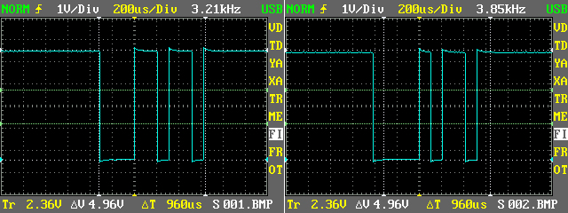
This is useful, and maybe even essential to some of your projects, when you want to see, for example, what the signal coming out of a circuit looks like.  It also can accept a Micro SD card, on which you can save a large number of waveforms.  You don’t even have to remove the card to examine the waveforms if you are powering it via USB from your PC – it can be seen as another device as if it was just another drive on your system.

Here are a couple I prepared earlier:


So you can see how useful this could be for inserting pictures into a document like this one – and it was.  Of course, all the necessary data is also recorded and displayed, to allow you to fully assess the waveform you have captured.


4. The Arduino


On reading all about the Arduino chip, I discovered the Arduino, a fully assembled board which allows you to program the ATMega chip from your PC.  Here is one form of the Arduino, identical to the one I bought (the Arduino Uno R3):
The Arduino has free-to-download software called the Arduino IDE (Integrated Development Environment – ie software).  Here’s what it looks like on the PC screen:


The image above shows two windows I put side by side.  The right-hand side of the picture includes a second window, an image of the Serial Monitor.  On the left is where you do all your coding.  It’s actually in the C language, but has been presented so that you only have to bother about the code, and not all the fussy stuff you need in C or Java.  Just load up the “Bare Essentials” sketch (the skeleton code you need - the individual programs are called ‘sketches’) and put your nitty gritty code in. 

The nice thing about this kind of coding, is that you don’t have to read a book on computer programming in a particular language, with all that laborious stuff on types of variables etc.  However, you will have to learn about all that if you get in deep, but if you’re a beginner, not just yet.  The whole approach to open source hardware and software, is learning by doing. 

You have loads of examples already written and freely available, and you’re allowed to copy all or parts of somebody else’s circuit or code, and by doing that, you’re learning what the code is doing and what the components in the circuit are for.  Then you can adjust the circuit or the code to get it to do exactly what you want it to do.  


And the best news of all – you can also run the Arduino IDE on the Raspberry Pi.


3. The Gertboard

Then came the Gertboard, an input/output extension device for the RasPi.  The one I got was a complete kit, so I had to get a new soldering iron, with all the accompanying bits and pieces, but I found that putting the thing together was very enjoyable.  I haven’t fully put the Gertboard through all its paces, but I have it continually hooked up to my Pi, and it’s constantly flashing its 12 red LEDs in every imaginable sequence:


Of course, I had to make the Gertboard do this flashing of lights, and this involved getting stuck into some code – another enjoyable exercise.  Here’s the Gertboard, which has a footprint about twice the size of the RasPi:

The kit came with a 26-wire ribbon cable which connects the RasPi to the double row of pins at the very bottom of the above image.  You can now buy the Gertboard fully assembled, but I found a great sense of achievement in soldering it all together.

There are a number of test programs available for the Gertboard, which I will eventually get round to running.  I couldn’t run them all just after building, because you need some more components, like DC motors, LEDs, breadboards etc.  A good starting point for the Gertboard is at http://www.raspberrypi.org/archives/411.

Now one attribute the Gertboard has is a micro controller, the long black chip at the bottom left of the image above.  The chip is an ATMega328P, which in itself, is an amazing thing.  Not as smart as the processor on the RasPi, but pretty powerful nevertheless.

On looking into the ATMega328P, also known as the Arduino chip, I found yet another distraction from the Raspberry Pi – programming micro controllers.  Here's a picture of the Arduino chip:

It’s only about an inch and a half long, but it’s amazing.


2. The Raspberry Pi


When I heard, just over a year ago, about the Raspberry Pi, I thought I would just have to get one. (Well over a million have been sold in the year or so since their release).  The Raspberry Pi Foundation has recently been described as the fastest growing computer company in the world.  The RasPi needs no introduction – there is more than adequate information out there on the web.  Its web page is http://www.raspberrypi.org/, and this includes an extensive forum on all aspects of the RasPi.

I’ll just say that the Raspberry Pi is a Linux computer with a footprint roughly the size of a credit card.  It’s cheap and easily obtainable, and importantly, it provides a set of pins allowing connection to physical devices.  You can program it to make things happen!  You can flash lights, drive motors, control robots, do things over the web, and much, much more.  Here is a picture of the RasPi:


I’m not going to take you through it, because a complete description of the various parts of the Raspberry Pi has been done many times on the web.
  
However, if you are serious about starting a hobby, you’ve got to make a few investments, and although I find myself continually buying stuff, it’s not expensive, nor does it occupy much space.  Nor is it difficult – this is a new route to getting young children skilled up in computing – and it’s working very well indeed.  Nor is it unsafe – as long as you’re not using voltages more than a few volts.  The main hazard at the beginning is probably the hot soldering iron.
Setting it up next to my PC is ideal as you are always looking up the internet on all kinds of related things.  Here is a picture of the desktop of my Raspberry Pi:

I of course had to buy a small TV, and find a power supply, keyboard and mouse.  That’s only the beginning of the shopping list, but the most expensive accessory is probably the TV itself, and everybody’s already got one, so you can use your family TV. 


The operating system is Raspbian Wheezy, an optimized version of Debian Linux, downloadable free of charge on a regurlarly-updated basis from http://www.raspberrypi.org/downloads


1. A New Hobby - Physical Computing


This is a page about my latest hobby – physical computing.  I have always been interested in computing, and also electronics, and although I studied both in the past, while I had a fair bit of experience in writing computer programs, I didn’t have much opportunity to get hands-on with electronics. 

I have since realised that electronics as a hobby is extremely accessible, with information galore on line, and any number of suppliers of electronic kits and components.  You can get all sorts of sensors, from ultrasound to infra red, radio, light, and a host of other technologies, like accelerometers, GPS and so on.  It’s an opportunity to work with and understand the technology behind all sorts of gizmos. 


The concept of “open source” hardware and software means that there is virtually no end to the amount of information and advice available through forums, on the web.  Additionally you can get stuck in straight away and learn as you go.


The first few posts will be of a general introductory nature, mainly describing my basic tools, power supplies etc, but I hope to move on to more detailed descriptions, giving code listings, circuit diagrams, etc - at least that's the plan!
The other reason is if my breadboard fumblings are of any use to anyone else who is either thinking about starting or has already started - please feel free to follow my path.
If any of my ramblings are inaccurate, then please let me know.  Don't forget - I'm on the learning curve too.


So - I thought I would Blog all this - for a couple of reasons - for my own record - because some of my early projects which I was quite proud of, out of necessity had to be dismantled to make way for new projects.  Alas, I hadn't documented them.  


Another reason - in the tradition of open source hardware and software - if it's any use to anybody out there - use it!!